NEW ! Errors
revealed, see at the bottom of this page.
*****************************************************************
You can't sell a preamplifier without a power amplifier
that join it.
History
When you have a good amplifier like the Puccini, it's easy to convert
it into a "power only" stage; so we did with the Donizetti.
The goal was to have the same sonic quality, but with the ability to
drive heavier loads. But what if you want "mo'power" ?
Well, the first approach is to increase the secondary voltage of the
power transformer. This in turns ask for an increase of the thermal stability,
for more VA of the transformer, etc.
But with the Puccini diagram is quite impossible to goes high with
the output voltage, because the zener floating power supply limit the voltage
swing to less than 60Vpp, i.e. near 50W.
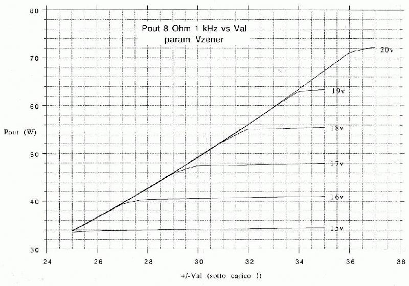 Output
rms power vs DC power supply with Vzener as parametric value (simulation)
So the first change in the original diagram is to increase the value
of the zener diodes from 16v to 18v.
Output
rms power vs DC power supply with Vzener as parametric value (simulation)
So the first change in the original diagram is to increase the value
of the zener diodes from 16v to 18v.
It's now time to download
the zipped poscript (630KB) file of the Donizetti power amplifier.
From this it's easy to see the change in value of D6/D7/D8/D9 (add
100 for right ch) that let the IC1 power supply to float up to twice the
value of the zener diodes.
With this configuration the output power is 20% increased (60W / 8
ohm); for a tighter control on low value loads, power supply capacitor
value has been increased (6x4700uF each channel, instead of 4x4700uF).
The transformer power is now 200VA each channel, with the AC value
of 56Vac (center tapped) instead of 50Vac.
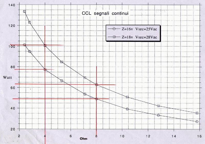 This
is a measurement of the increase we obtain (Power vs Load) from a Puccini
to a Donizetti
Well, for a 4 Ohm load we have a near 40% of increase in power. Not
so bad, indeed !
In order to remain into a security heath level we increased the heathsink,
formerly obtained in the standard Puccini with the chassis; now it's a
real black and big vertical heatsink, with holes on the top and the bottom
of the Donizetti chassis for a "chimney" effect.
A pair of relays (one per channel) are now acting as "protection
cut-off", each driven by a DC fault system as in the standard Puccini
(again one per channel).
The amplifier board condition is controlled even via the "Sleep-Awake"
board, where the stand-by circuit receive the piezo button signal and drive
the relays in consequence.
This
is a measurement of the increase we obtain (Power vs Load) from a Puccini
to a Donizetti
Well, for a 4 Ohm load we have a near 40% of increase in power. Not
so bad, indeed !
In order to remain into a security heath level we increased the heathsink,
formerly obtained in the standard Puccini with the chassis; now it's a
real black and big vertical heatsink, with holes on the top and the bottom
of the Donizetti chassis for a "chimney" effect.
A pair of relays (one per channel) are now acting as "protection
cut-off", each driven by a DC fault system as in the standard Puccini
(again one per channel).
The amplifier board condition is controlled even via the "Sleep-Awake"
board, where the stand-by circuit receive the piezo button signal and drive
the relays in consequence.
Like the Bellini preamplifier, a three colour LED show the status of
the amplifier (Green is OK, Red
is Stand-By, Orange is Fault)
If you have time ...
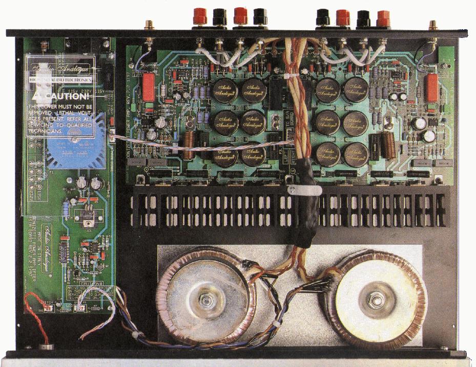 Click
here for an internal view of the Donizetti power amplifier
Click
here for an internal view of the Donizetti power amplifier
Errors revealed, or "How
to modify my amplifier"
At the beginning of this adventure, I had not so much time to deeply
investigate on amplifier's characteristic; yes, I made some standard tests
(e.g.: power out, -3dB limits, THD @ 1kHz, and so on), but I never had
time to see what really happen with limit conditions. The products sounds
well, and this were OK for me.
Only when I sold my share of the Audio Analogue I decided to spend
some time on characterizing the power stage (I remind you that, except
some minor change, the diagram is the same for Puccini, Puccini S.E. and
Donizetti; and you can apply the theory of this modification to all these
products).
So I removed the dust from my Sound Technology 1700B THD meter and
from my H.P. 3652A FFT analyser, and I began to play with a prototype of
Donizetti power amplifier.
Error #1 (this mod apply
even to Puccini & Puccini S.E.)
This is what you can have from a NORMAL Donizetti (as you can buy from
a dealer):
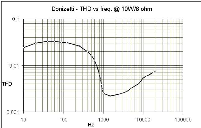 The
THD vs Freq. @ 10w/8ohm
Not so bad, but not even normal ! If is usual to see the THD raising
with frequency at the edges, I've never seen a buckle like this !
Sure I never suspect this, because I always made measurements at about
1kHz or higher, not at 100Hz.
Anyway, was not easy to understand this increase of THD; but after
some PSPICE simulation all was clear !
Grab the diagram (always the left ch.), and follow me:
the signal coming from IC1 drive the power transistors via C28 and
C29; but for DC stability, there is also a DC loop that make use of R14,
R15, D10 and D11; if the AC signal is more than 1kHz, the capacitive reactance
of the capacitors is low enough to short-circuit D10 and D11 (I mean that
you'll never find more than 0.7v of AC signal at diode's terminals).
But going down with the frequency make the reactance growing, until
the voltage reach 0.7v; at this point the diodes start conducting, and
you know that a diode is all but a linear device ! So THD start to increase,
even if there is a feedback that try to kill it. But feedback is not infinite,
and cannot do much more of this.
Well, the solution is simple: change the value of C28 and C29. Here
you'll see how the distortion decreases with the capacitors increasing.
The
THD vs Freq. @ 10w/8ohm
Not so bad, but not even normal ! If is usual to see the THD raising
with frequency at the edges, I've never seen a buckle like this !
Sure I never suspect this, because I always made measurements at about
1kHz or higher, not at 100Hz.
Anyway, was not easy to understand this increase of THD; but after
some PSPICE simulation all was clear !
Grab the diagram (always the left ch.), and follow me:
the signal coming from IC1 drive the power transistors via C28 and
C29; but for DC stability, there is also a DC loop that make use of R14,
R15, D10 and D11; if the AC signal is more than 1kHz, the capacitive reactance
of the capacitors is low enough to short-circuit D10 and D11 (I mean that
you'll never find more than 0.7v of AC signal at diode's terminals).
But going down with the frequency make the reactance growing, until
the voltage reach 0.7v; at this point the diodes start conducting, and
you know that a diode is all but a linear device ! So THD start to increase,
even if there is a feedback that try to kill it. But feedback is not infinite,
and cannot do much more of this.
Well, the solution is simple: change the value of C28 and C29. Here
you'll see how the distortion decreases with the capacitors increasing.
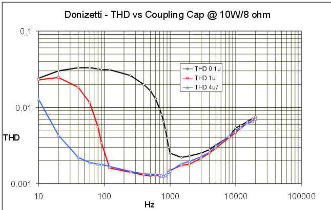 THD
vs Freq. param C28 & C29 value: it works !
THD
vs Freq. param C28 & C29 value: it works !
Don't stop at 4u7; consider that 10watt is not the worse case. See what
happen changing the power:
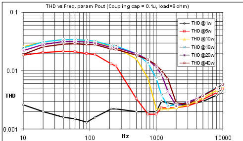 In
the old configuration, here is the THD vs Freq. param Pout
In
the old configuration, here is the THD vs Freq. param Pout
Ok, stop playing, I made all the tests for you: the best value is 10uF
polypropylene.
I know is not cheap nor simple (they are BIG capacitors), but using
63v models you can fit'em under the pcb, without removing old caps.
For access to the solder side of the pcb simply unscrew 3+3 screw and
pull out the cable between the sleep-awake board and the power amplifier
board; then you can "spin" the pcb without unsoldering any cable
but the input wires: unsold them from the pcb side.
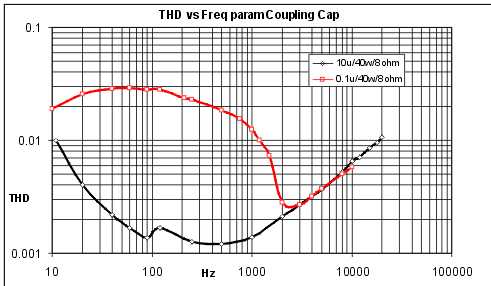 This
is what (at least!) you can obtain: a neat "factor 10" of reduction
in the THD !
This
is what (at least!) you can obtain: a neat "factor 10" of reduction
in the THD !
Error #2 (this apply only
to Donizetti)
This is a stupid modification: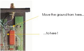 In this way the S/N ratio of the right channel is increased of about
10dB; you can apply this mod to the left channel too, but the S/N in this
case remains the same; it seems there is a field effect of the little transformer
that prevent the improvement.
In this way the S/N ratio of the right channel is increased of about
10dB; you can apply this mod to the left channel too, but the S/N in this
case remains the same; it seems there is a field effect of the little transformer
that prevent the improvement.
Error #3 (this is not a mod
but a WARNING, and apply even to Puccini & Puccini S.E.)
Just the moment that you think to have nice dreams, it happens ! We
always use a Texas NE5534AP, and we never had problems; but give a look
to what can happen if you decide to use a Philips (!) NE5534AN:
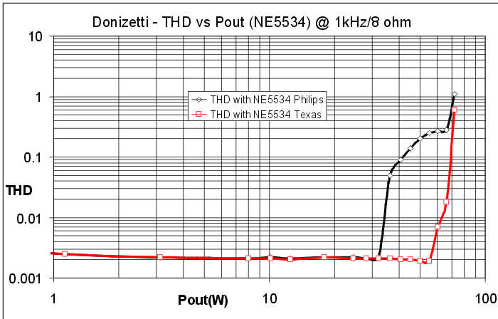 Incredible
things happen when you don't find any more the chip you've always used
!
I think this problem come from the different behaviour of the die when
the inputs are near the power supply.
Incredible
things happen when you don't find any more the chip you've always used
!
I think this problem come from the different behaviour of the die when
the inputs are near the power supply.
By the way, I've tested some more chips on the same diagram; in details,
chips that works are:
NE5534AP by Texas (THD@40w/8ohm/20kHz =
0.0105%)
TLE2071CP by Texas (THD@40w/8ohm/20kHz
= 0.0670%)
OP176G by Analog Devices (THD@40w/8ohm/20kHz
= 0.1200%)
LF356N by National Semiconductors (THD@40w/8ohm/20kHz
= 0.1020%)
SSM2131P by PMI (THD@40w/8ohm/20kHz = 0.1280%)
Each one gives different results, considering not only the generic
THD but also the "sonic impression"; try them and drop me an
e-mail with your impressions.
(As you see the old 5534 seems to be the best !)
Error #4 (this is a general
rule for all Audio Analogue amplifiers, but can apply only to Donizetti
for thermal problems)
The quiescent current is too low ! As well explained
in the Puccini Section, it has been chosen a current of about 20mA per
devices.
It's always a "compromise" problem;
in that case (Puccini) there was the problem of the "little"
heathsink, so was impossible to have higher current.
When Donizetti was born, no ones remembered to
increase it, so also today is 20mA/device.
That's wrong ! For good results it must doubled
to 40mA.
Having a digital multimeter (200mV DC full scale)
put the NEGATIVE probe to the positive (RED) output binding post; put the
POSITIVE probe to each of the power transistor's emitter; find the ones
(of the four) having the absolute higher value (e.g.: 6mV, don't care of
the sign) and turn VR1 (VR101 for the right ch.) clockwise until you read
about 12 mV with the DVM; then again check if what you're measuring is
the "highest value" transistor; after some minutes bring the
voltage to about 13mV. For the other channel remember to move the NEGATIVE
probe, otherwise you'll read the Iq PLUS the off-set voltage of the previous
channel.
Back to the home page