Aida is the name of a particular version of the Puccini S.E. selected by Opera, an Italian speaker maker who wanted to have an integrated amplifier to sell together with his products.
There are two important differences between the Audio Analogue original product and the Aida:
A minor difference (aesthetic but also mechanical) is the change of position between knobs: in the Aida the volume is at the left, the input selector at the right.
Let's us start with the protection; here is the diagram:
Let us analyse the upper part of the diagram: the circuit works sensing the current in one of the two power transistors (assuming there is a good sharing of it due to the emitter resistors); the voltage thus obtained is reduced of about 20% by the R?/R73 divider.
Being the output current DC, this voltage would directly go to the Q6
base, bringing this transistor in conduction and then shunting the signal
from the darlington's bases. In this case the maximum output current per
transistor would be something more than 2 A.
This is a safe value for the transistor (worst case is 60W power dissipation),
and by the way is a value that brings the rail fuse to a quick dead (the
current is 4 A, remember the DOUBLE output devices !).
But in dynamic conditions (e.g. sine) the 4A value is peak, equivalent
to less than 3 Arms output current.
For short periods this amplifier can give MORE than 3A (with 4 ohm load
the current is near 5 Arms), so we need some circuit that "sense"
the load and let the current be higher if the load is not a short circuit.
This circuit is the "Fold-Back" protection, and the salient
components are R69 and R71. These resistors act as a divider that changes
its value depending by the output voltage. In our case, if the voltage
is "not so near zero" the load is not a short-circuit and the
divider works, reducing the voltage that will go to the base of Q6.
In the other condition (there is a short-circuit, and the output voltage
is near zero) the divider works "less than before" (the lower
side of R69 is at ground potential), and the WHOLE voltage available goes
to the Q6's base.
The result is visible in this plot:
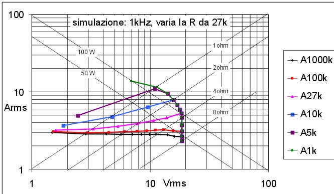 Here
is a simulation of how the value of R69 decide the point of fold-back
Here
is a simulation of how the value of R69 decide the point of fold-back
In this graph the value of R71 is assumed to be 1k, bringing to different
values of R69, the optimal value being 27k instead of 39k if R71=1k5; diodes
D14 and D16 are needed for avoid the reversal of voltage around Q6 when
the output is going near the negative value.
With the value given, the fold-back point start at just a little less than
4 ohm, allowing a power near to 100W to be reached.
Another important component is C36, that with R71 act as low pass filter
(time constant is 0.15mS): with it all transient higher than 1kHz will
not turn on Q6, avoiding the clipping of the burst.
A good view of what happen with different frequencies can be seen in the
following graph:
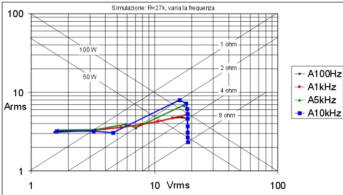 Here
a simulation of the Fold-Back point that change with the frequency
Here
a simulation of the Fold-Back point that change with the frequency
It is clear how, for signals above than 1 kHz, the output current become higher, and in the same way, if there are fast slewing signals, nothing will happen (the load can go down till 2 ohm); for signals lower than 1kHz however the minimum load must be at least 4 ohm.
In the final product the divider (R?/R73) has not been implemented; results are in the following graph:
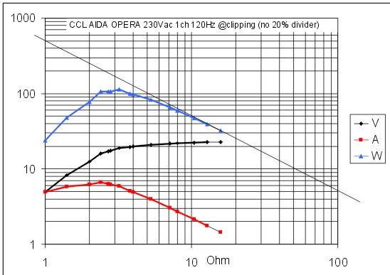 Measurements
over a prototype: how Voltage, Current and Power change with the load
Measurements
over a prototype: how Voltage, Current and Power change with the load
Remember: if you try to use this kind of protection with REAL LIFE loudspeakers NEVER forget to use diodes D18 & D19; when you have an inductive load (e.g.: always!) and the protection start working, you'll have peaks higher than power supply value; so D18 and D19 avoid the burning of output transistors for Vceo overcome and/or reverse bias.
An interesting mod: visual clipping
In all the amplifiers using Darlington power devices (in
a single chip or with discrete components) it is possible to have a visual
indication when the current protection goes on: simply substitute diode
D14 (D15 in the negative side) with an optocoupler as the 4N27 family.
The output of this will "trigger" a 555 timer (TC=0.1S) in order
to have an indication long enough for the eye's persistence.
This circuit works because Q6 saturation voltage PLUS the collector's diode
drop is LOWER than the double Vbe of the power output transistor.
Here you can see the diagram:
In a stereo integrate amplifier you can choose to make four circuits with the 555 timer (and so four LEDs), or only one 555 circuit (assuming all the optocouplers' pins n.5 are connected together) that will blink every time with no indication about "who's who".
The rest of the circuit
It's now time to download
the zipped poscript (58KB) file of the complete Aida integrated amplifier.
As you can see, the circuit is the same of the Puccini S.E. but
some component's type, in order to obtain a different sonic imprint.
These are R14, R15, R46 in the preamplifier section and R16, R21, R49 in
the power stage (add suffix 100 for the Right channel).